The Custom House elevator sheets recover local overhead steel and exact floor datums. The whole-building upper frame remains a provisional reconstruction while its framing plans are being sought.
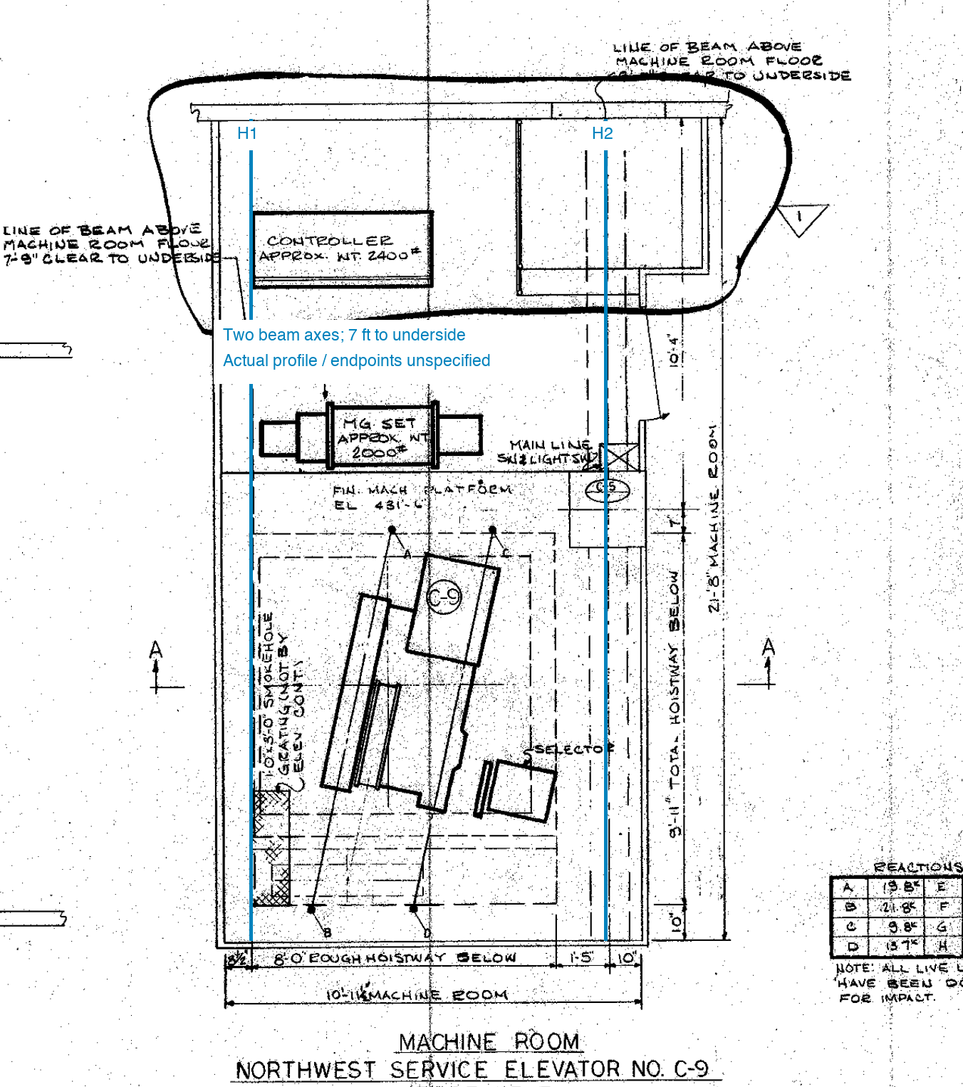
Source detail only. The two C9 beams below are shown in their machine room's local drawing coordinates. Their position and orientation in the whole-site model have not been recovered.
Corrected source levels
EL-2, PDF page 707. Elevations use the original project datum; the study's vertical origin is EL310.
Source level
Elevation
First / concourse
310 ft
Second / plaza
332 ft
Third
352 ft
Fourth
364 ft
Fifth
376 ft
Sixth
388 ft
Seventh
400 ft
Eighth
413 ft 6 in
Finished machine-room floor
430 ft 6 in
Local service machine platform
431 ft 6 in
Local bulkhead roof
440 ft 6 in
The eighth floor is 13 ft 6 in above EL400. Earlier 415 / 430 / 440 readings are corrected here. Machine-room and bulkhead datums do not establish a full-building roof perimeter.
C9 machine-room overhead beams
Lines show beam axes, not measured flange widths. Displayed spans follow the dimensioned room; actual beam endpoints are unspecified. Local trace precision is about ±0.2 ft. A rendered I-section is a representative visual choice.
Original C9 plan, annotated
EL-2 identifies two overhead beam strips in the northwest service-elevator machine room and gives 7 ft clearance to their underside. The source is an elevator detail, rather than a full upper-floor structural drawing.
C10 section B-B and passenger section C-C also show hoist/trolley beams. Their source undersides are EL438 ft 2½ in and EL437 ft 10½ in respectively; their plan axes have not been uniquely assigned. The original contract drawing is dated 6 December 1968.