The hotel and plaza building frames
WTC 3, 4, 5 and 6 retain their reviewed steel members, building grids and individual source records. Selecting a member shows its recorded source and section where available. The whole-complex view uses the same factories as the structural viewers.
Custom House upper steel: drawings and review ↗
Retail above the main mall
The main mall was at concourse EL310. Retail and services also occupied parts of the buildings bordering the plaza, at EL332. This first addition traces the west portion of WTC 5’s plaza floor: three older tenant shells, a public gallery, the recessed plaza lobby and its entrance.
Use Plaza retail shell for the cutaway. The named stores in the later directory are location evidence; their exact partitions and multilevel layouts remain to be reconciled.
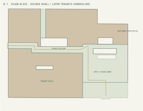
Tan: older tenant shells. Green: gallery, lobby and porch. Violet: east study cut and reserved escalator interface. The cut walls show interiors without adding the upper office building.
Later retail locations · July 1999 directory
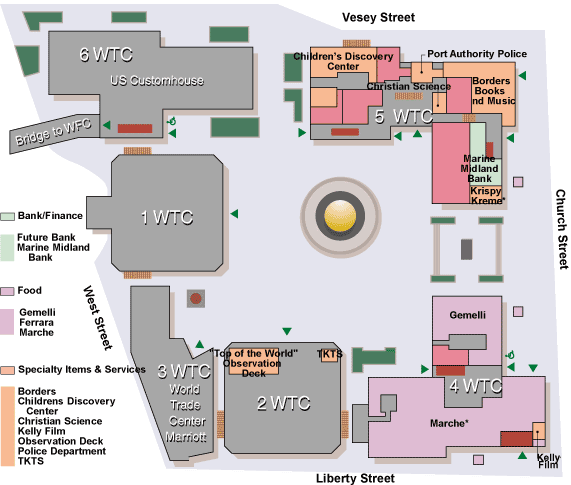
The WTC 5 labels include Children’s Discovery Center, Christian Science, Borders Books and Music, Marine Midland Bank and Krispy Kreme. WTC 4 includes Gemelli, Marché and Kelly Film. The graphic also distinguishes public/service areas and shows TKTS and the observation-deck entrance near WTC 2.
The mirror owner records downloading this World Trade Center graphic in July 1999. It is a schematic directory, not a dimensioned tenant plan or a September 2001 occupancy schedule. Its store boundaries have not been projected into the architectural model.
Directory provenance ↗ · Corroborating Port Authority directory in the Willis report, PDF45 ↗
Architectural shell · A-E-22
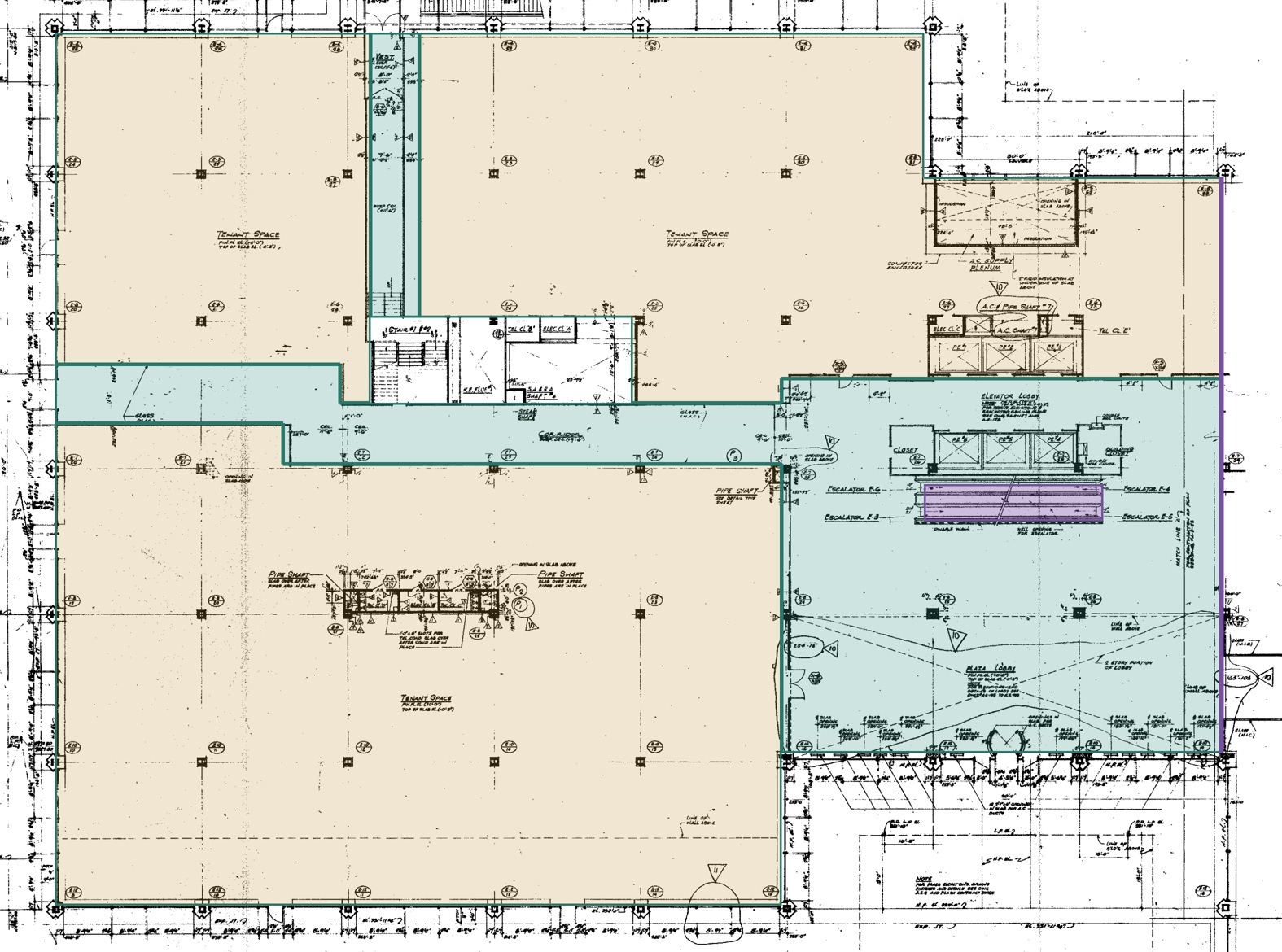
The existing six-control registration fixes this trace to the same plaza and concourse coordinates. The original sheet identifies tenant space, public corridor, plaza lobby, lift/service cores and the E3/E4 opening. The December 1990 receipt stamp is not an as-built date.
Floor slabs, cut walls, glass boundaries, selected columns and a simplified revolving entrance give the shell depth. Wall heights, profiles, glazing divisions and door sizes remain display assumptions. Later store subdivisions, the east and south wings, internal retail stairs and the complete plaza/concourse escalator connection are still open. The guarded opening is not a completed passenger route.
Trace and assumptions ↗ · Full architectural sheet ↗
Inside the concourse
The lower tower lobbies open into a connected shopping level at EL310, 22 feet beneath the plaza. The model traces the cross passage outside WTC 1, the turn toward WTC 2, the southern loop, PATH hall, the Church Street passage and northern branches. Thirty-six tenant envelopes frame the routes.
Use Concourse overview to inspect the open plan, or the three lower views to enter it. The optional ceiling envelope supplies provisional headroom for those views. Whole complex keeps the concourse present beneath the plaza; Open plaza reveals it without separating the floors.
Walking routes and shop boundaries
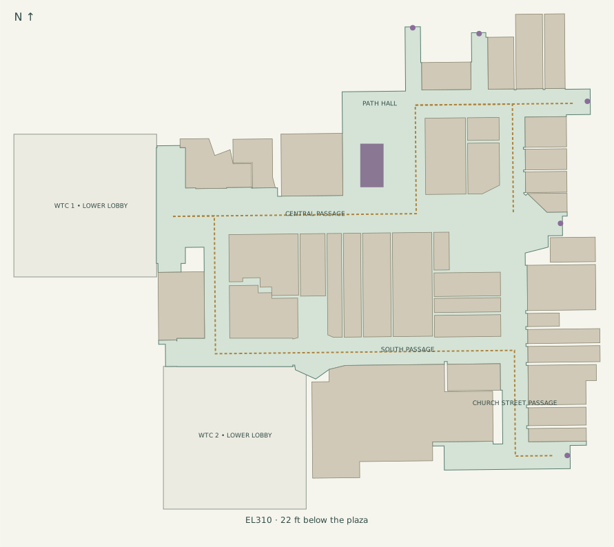
Green: public circulation. Tan: tenant space. Purple: PATH opening and unresolved connections. Gold: illustrative walking routes. Tenant names, storefront sections and ceiling height are not a verified 2001 fit-out.
Traced from the existing layout
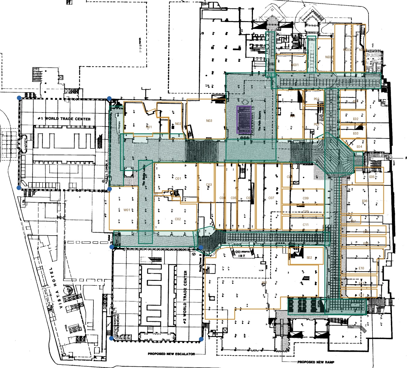
SKA56/84, Port Authority release 18324, PDF page 316. The original sheet also labels proposed ramps, a canopy, an escalator and northern entrance structures; those proposals are omitted. A-E-16 through A-E-19 corroborate the tower connections, tenant boundaries and PATH opening.
Eight tower-corner controls give an image-fit RMS of approximately 1.6 ft and a maximum residual of 3.1 ft. These are fitting residuals, not independent accuracy checks. Bounded floor joins meet the existing tower doors without moving the towers. Narrow aprons also close the small scan gaps at the review shopfront openings.
Trace, registration and assumptions ↗ · A-E-16 · WTC 1 and PATH ↗ · A-E-18 · between the towers ↗
Where the model ends
The PATH opening now meets the source-registered upper escalator bank. PATH journey exposes the descent through the underpass, mezzanine and platform access groups. Equipment rooms, service connections and the final 2001 operating arrangement remain unresolved. Purple markers identify the northern and Church Street interfaces; the street stairs, subway interiors and changes of level beyond them remain unresolved.
Wall and storefront heights, glazing divisions, generic review openings, material colors, floor borders, column sections and the flat 12.5 ft ceiling are display assumptions. The model does not reproduce merchandise, branded shops, services or a verified September 2001 renovation state.
NIST · concourse circulation and lobby plans ↗
The existing lower model, now in this study
The PATH railway, both tower basement frames, foundation references and original bathtub wall share the same survey frame as the lobbies. Their scale, orientation and elevations are preserved. Below ground removes the upper floors from view; PATH tracks also hides the tower framing to reveal the railway.
The imported model includes five station tracks, three platform bodies, both approach routes, 272 basement column/support components, 1,167 framing members, four South Tower core-transfer trusses, bounded foundation concrete and footing-plan references. The transparent wall uses the existing nominal three-foot thickness.
Frozen model and source hashes ↗
Follow the passenger route
Concourse EL310 → underpass EL274 → mezzanine EL264′3″ → platforms EL250. The model now includes the long upper bank, underpass floor, short lower bank, mezzanine fare-control lines and six platform access groups. Use PATH journey and its four stops to inspect the descent.
A-P-88 / 88-A register the mezzanine to the original N/W survey grid. A-P-89 joins the underpass at its match line; A-P-95 and A-P-96 establish the vertical sections. The upper bank on this revision has nine escalators P19–P27 and stair P9. The lower bank has two outside escalators and six intervening stair bays, several labelled for future escalators. These are the drawing’s arrangements, not a verified September 2001 operating schedule.
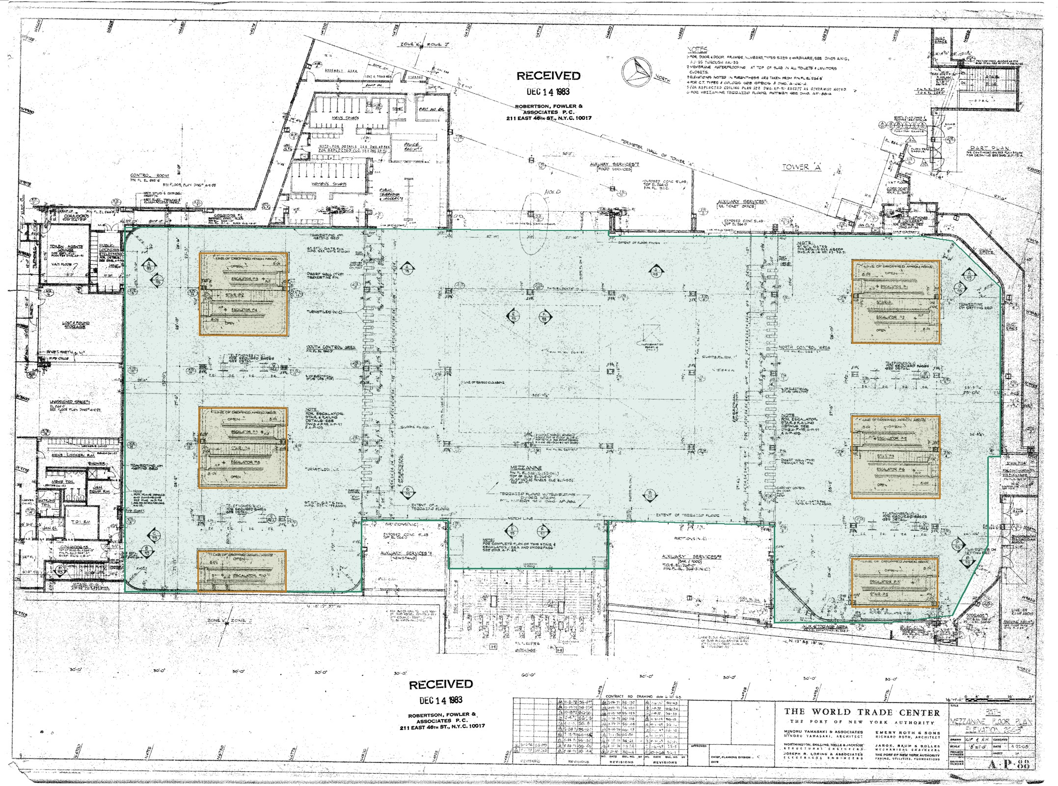
A-P-88 · public hall and access groups
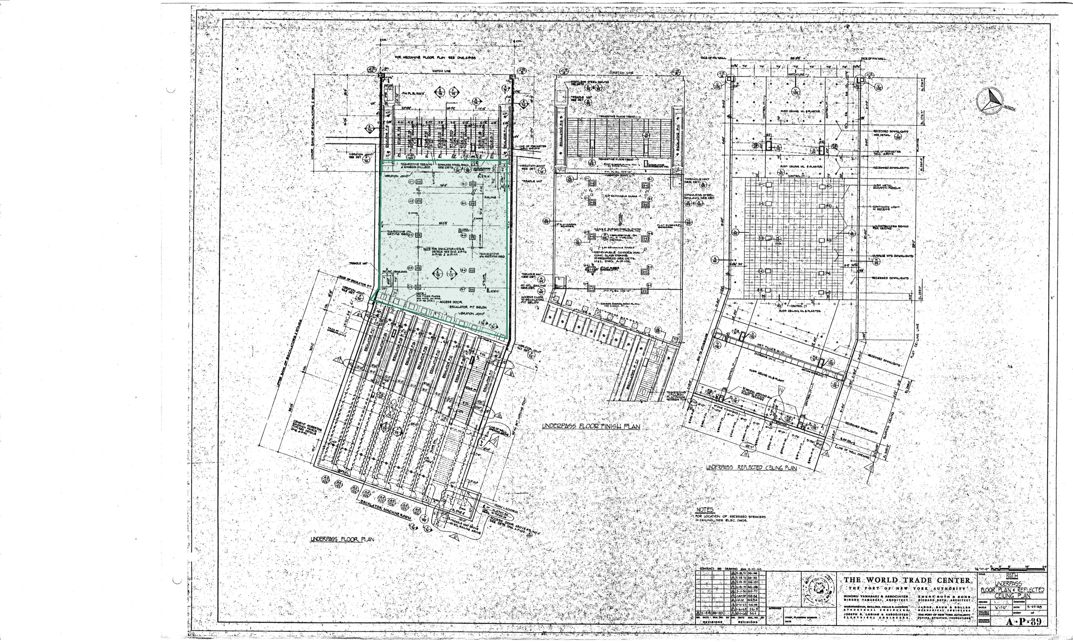
A-P-89 · bent underpass and both banks
A-P-95 · platform connections ↗ · A-P-96 · underpass sections ↗ · Coordinates, source controls and assumptions ↗
Survey-fit RMS: N 0.46 ft; W 0.17 ft. The traced match line measures 58.52 ft against a printed 60 ft; this 1.48 ft discrepancy is retained, not hidden by moving the tracks. A small local EL250 landing joins stair P5 to the previously coarse platform A body. Finishes, fare-device count, guard sections, stair subdivisions and column sections are provisional. The roof is omitted for the cutaway. Full machinery rooms and auxiliary connections remain open.
One vertical datum
| Level | Source elevation | Below concourse |
|---|
| Plaza / upper lobby | EL332 | 22 ft above |
| Shopping concourse | EL310 | 0 |
| B1 · Tower A service level | EL294 | 16 ft |
| B2 | EL284 | 26 ft |
| B3 | EL274 | 36 ft |
| PATH underpass · A-P-96 | EL274 | 36 ft |
| PATH mezzanine · A-P-95/96 | EL264′3″ | 45 ft 9 in |
| B4 | EL264 | 46 ft |
| B5 | EL253 | 57 ft |
| PATH platform · R-65 section | EL250 | 60 ft |
| PATH top of rail · R-65 section | EL246′6″ | 63.5 ft |
| B6 | EL242 | 68 ft |
B1–B6 are Tower A architectural reference elevations, not uniform site-wide slabs. The local PATH rail datum is projected flat through the approaches; their grades remain unresolved. EL242 is not a bedrock surface or surveyed wall toe.
What remains open
The principal passenger route is in place. Auxiliary stairs including P6, complete machine rooms, service passages, lifts and final 2001 alterations still need reconciliation. Full basement floor plates, interior rooms, complete footing depths and the bedrock surface have not been reconstructed. The imported wall is displayed between EL310 and EL242, without claiming its full vertical extent.
The existing PATH review retains one conflict between a diagnostic vehicle envelope and South Tower column 301. This is not a verified train clearance envelope; the study preserves that unresolved condition. Construction tiebacks are an optional illustrative overlay from an earlier phase, hidden by default.
PATH plan reconciliation ↗ · Outstanding clearance review ↗ · South Tower core transfers ↗ · Bathtub and construction limits ↗
How people entered the towers
From the plaza: the main doors were on WTC 1’s east face and WTC 2’s north face. Each original entrance group had two revolving doors flanking two pairs of swinging doors. The plaza led into the mezzanine; paired lobby escalators connected it to the concourse 22 feet below.
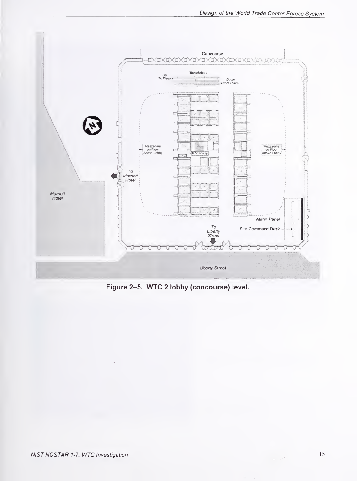
From below: the shopping concourse connected PATH arrivals and other mall routes to the lower lobbies. WTC 1 also opened toward West Street, and WTC 2 toward Liberty Street. NIST’s plans show side connections, including the Marriott; these later interfaces are not yet reconstructed.
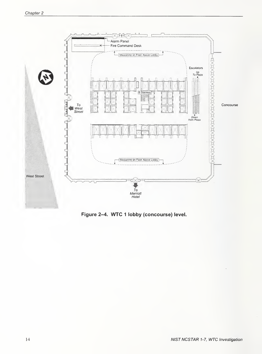
WTC 1 · lower lobby
WTC 2 · lower lobby
Alignment audit: the tower survey centers, orientation and EL310 / EL332 datums are retained. The coarse main-plaza trace missed WTC 2’s façade by about 3.7–3.9 feet at the central doors; a bounded infill now meets that threshold. At WTC 1 the difference is under one inch. This is a local model reconciliation, not independent proof of the whole plaza alignment.
Original four-bay entrance elevation ↗ · WTC 2 plaza door plan ↗ · NIST circulation account and plans ↗
Both lobbies now have architectural enclosures
Use Inside WTC 1 or Inside WTC 2 to inspect the balcony at eye level. Each now includes the marble core, shuttle-elevator fronts, four local elevator-bank passages, curved glass guards, window bays, entrance assemblies and paired escalators.
The shared A-AB sheets explicitly cover both towers. The reflected ceiling plan adds 64 curved plaster panels around each core, with simplified chandeliers. Ceilings turn on for the interior views and can be hidden for inspection from above.
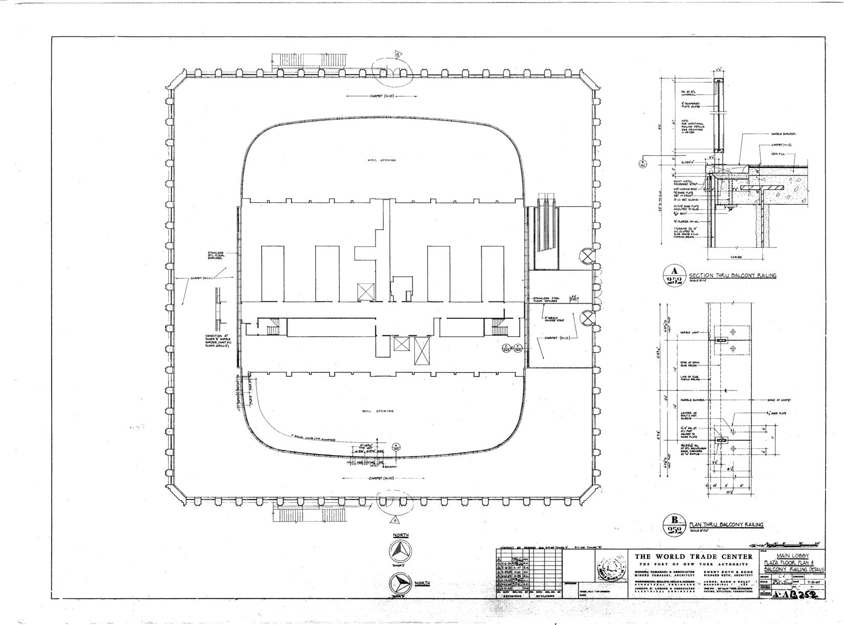
A-AB-252 · balcony guard and floor relationships
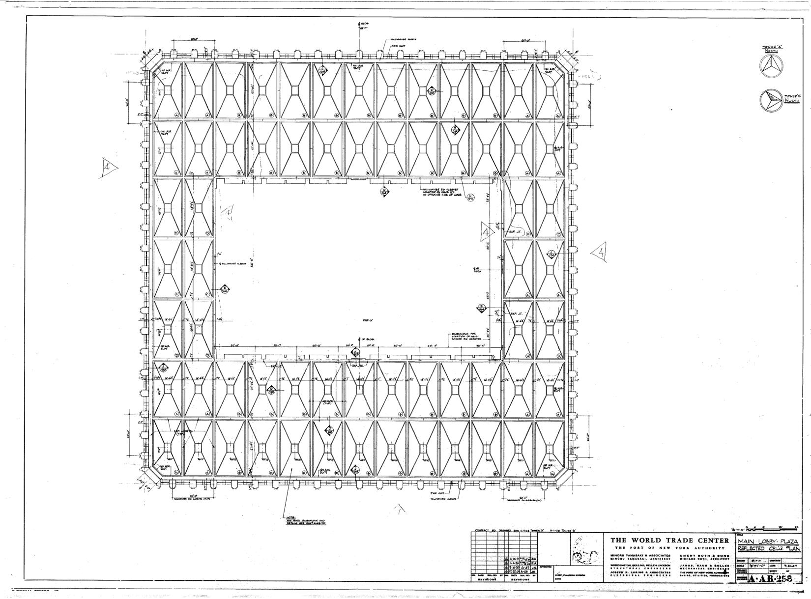
A-AB-258 · ceiling layout; A-AB-259 · panel sections
Escalator sections ↗ · Core wall sections ↗ · Window and entrance section ↗
This is a bounded architectural reconstruction. Door heights, small trim sections, finish tones, ceiling curvature and chandelier crystals are simplified. Glazing coverage at the lower concourse, internal stairs, signage, furniture, planting and later alterations still need work. The dated 19 August 2000 North Tower photograph is a visual check; it also shows finishes and movable elements beyond the original plans.
Inside the South Tower lobby
The concourse floor at EL310 sits below the plaza balcony at EL332. Two curved openings run along the east and west sides of the core. The paired north-side escalators connect the concourse to the balcony.
These surfaces follow Tower B sheets A-B-20 and A-B-22, with each drawing registered independently to the tower perimeter. The originals point north to the right. Green shows the floor envelope; amber shows the traced openings. The dashed balcony edges on the concourse sheet describe the floor overhead.
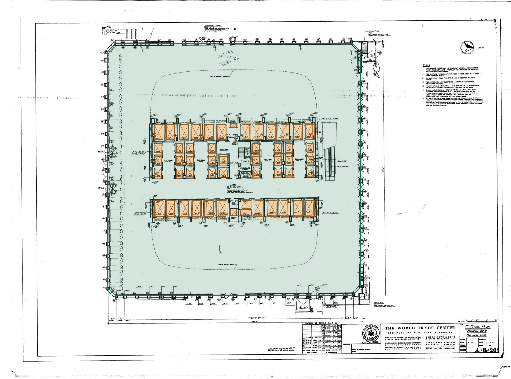
A-B-20 · concourse · PDF page 410
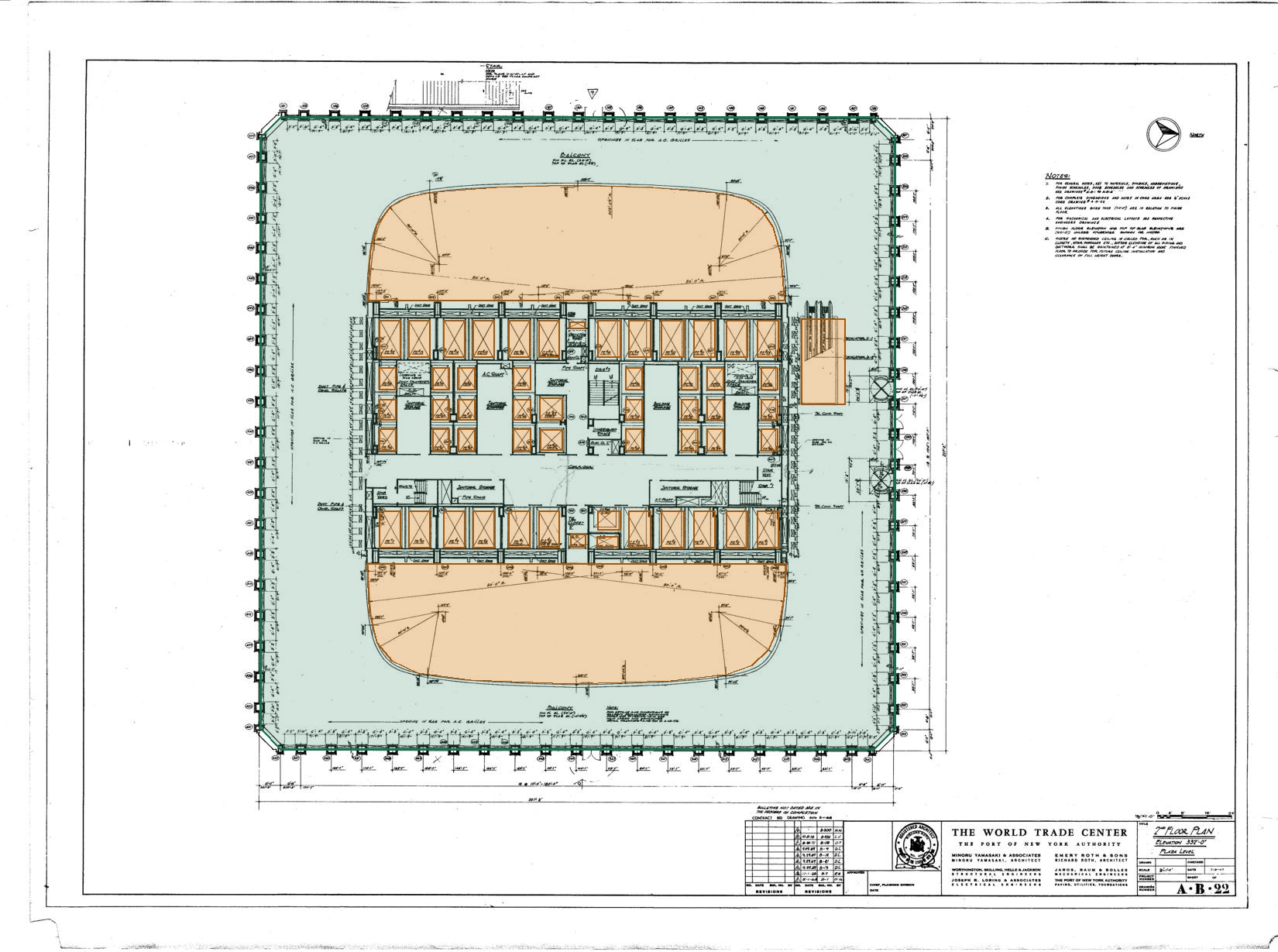
A-B-22 · plaza balcony · PDF page 413
Original design/revision plans, not verified 2001 as-builts. Manual traces carry an approximate 2 ft allowance. Floor depth, escalator treads and handrails are simplified. Study 11 adds the core enclosure, elevator fronts, balcony guards, glazing and entrance assemblies to both towers from the shared detail sheets. Internal stairs, machinery and later fit-out remain incomplete.
South Tower trace and assumptions ↗ · Original plaza sheet ↗
The towers now share the plaza’s coordinates
The WTC 1 and WTC 2 lobby geometry uses the shared site models, checked against the retained research snapshot. Their original survey positions, dimensions and lobby datums remain intact; a single translation places them in this study’s frame. Tower coordinates retain their original survey frame.
WTC 1: column trees, concourse floor and plaza balcony with traced atrium openings. WTC 2: column trees plus independently traced concourse and plaza floors, two curved atria, and paired escalators at the north side. The South Tower extension uses its own A-B-20 and A-B-22 plans.
Lobby cutaway hides upper lobby floor plates and clips the frame above EL426 so the ground relationships stay visible. Full towers restores the height. Tower plaza floors stay at EL332 when a ground scenario changes.
Ground edges were coarsely traced independently and can differ from the tower faces by a few feet. These joins still need architectural threshold details; the tower geometry has not been stretched to fit them.
Frozen source files and hashes ↗
The functional ground layout
The main plaza now connects to four additional exterior stair banks, their upper walks, and lower approach courts toward West and Liberty Streets. The Vesey route and fountain terrace remain connected. The east court reaches a reserved transition band before Church Street.
Each stair has its own adjustable drop. The plan supports its location and approximate envelope; the model supplies a testable section. The Church transition is wirework only: the evidence reviewed so far does not settle its steps, slope or exact thresholds.
Church Street is a separate level
A-E-24 contains curb annotations around EL325–326. The relationship to the court’s finished edges has not yet been registered. This control tests a rounded street-level scenario; it does not turn the wire envelope into a verified ramp or stair.
C1 marks the separate WTC 5 concourse entrance served by E-1 / E-2 in A-E-24 and A-E-62. Those indoor escalators do not rise to the outdoor plaza like the Vesey pair.
What is covered
| Connection | Representation | Where it leads |
|---|
This accounts for the principal exterior routes reviewed in the available plans. It is not an exhaustive 2001 exit inventory, an accessibility assessment or a verified evacuation model. The Concourse plan tab now adds the principal interior walking routes. Unresolved street and transit transitions remain marked at their interfaces.
Where the additions came from
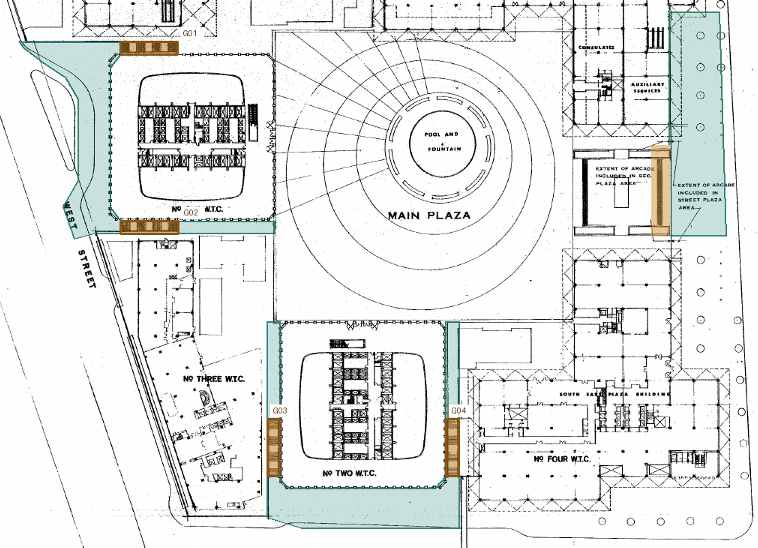
SKA55/84, PANYNJ-18324 PDF page 315. The adjacent site plan on page 314 corroborates the four banks. Green marks bounded exterior floor traces; amber marks stair envelopes and the Church transition reservation. The original image contains buildings for orientation.
The Port Authority’s May 1993 visitor map distinguishes concourse exits toward Vesey, Church, Liberty and West Streets. It supports route destinations but is not a scale plan of plaza stairs. NIST Volume 3 was retrieved; the reviewed map-divider pages did not yield usable local-area maps.
1993 concourse map ↗ · A-E-24 curb annotations ↗ · Access evidence and assumptions ↗
Where do the stairs and escalators go?
They connect the Vesey Street sidewalk below to the raised plaza approach above. The original upper plan shows a walk continuing west, then turning south beside two planter beds toward Austin J. Tobin Plaza.
Vesey Street lies north of the entrance. The adjoining frontage is WTC 5, with WTC 6 farther west across the passage; their steel frames are included in the complex viewer. Subway access is a separate lower connection. The reported link onward to the WTC 7 bridge remains outside this model.
The plaza-to-street connection is documented. The route and local walking surfaces below are an interpretation of older plans, pending confirmation against the 2001 condition.
Beyond the main rectangle
1 · North walk: the strip between the North Tower and northern frontage. 2 · East arcade court: ground between the eastern frontages, toward Church Street. 3 · Southeast approach: a short open strip beyond the main plaza.
The green outlines below record the earlier Study 05 additions. Study 07 extends their connections in the Access network tab. Amber lines trace eleven paving rays. Each new surface uses the upper plaza elevation for now. Local falls and unlabelled objects need further evidence; the Access network tab distinguishes the new stair scenarios from the unresolved Church transition.
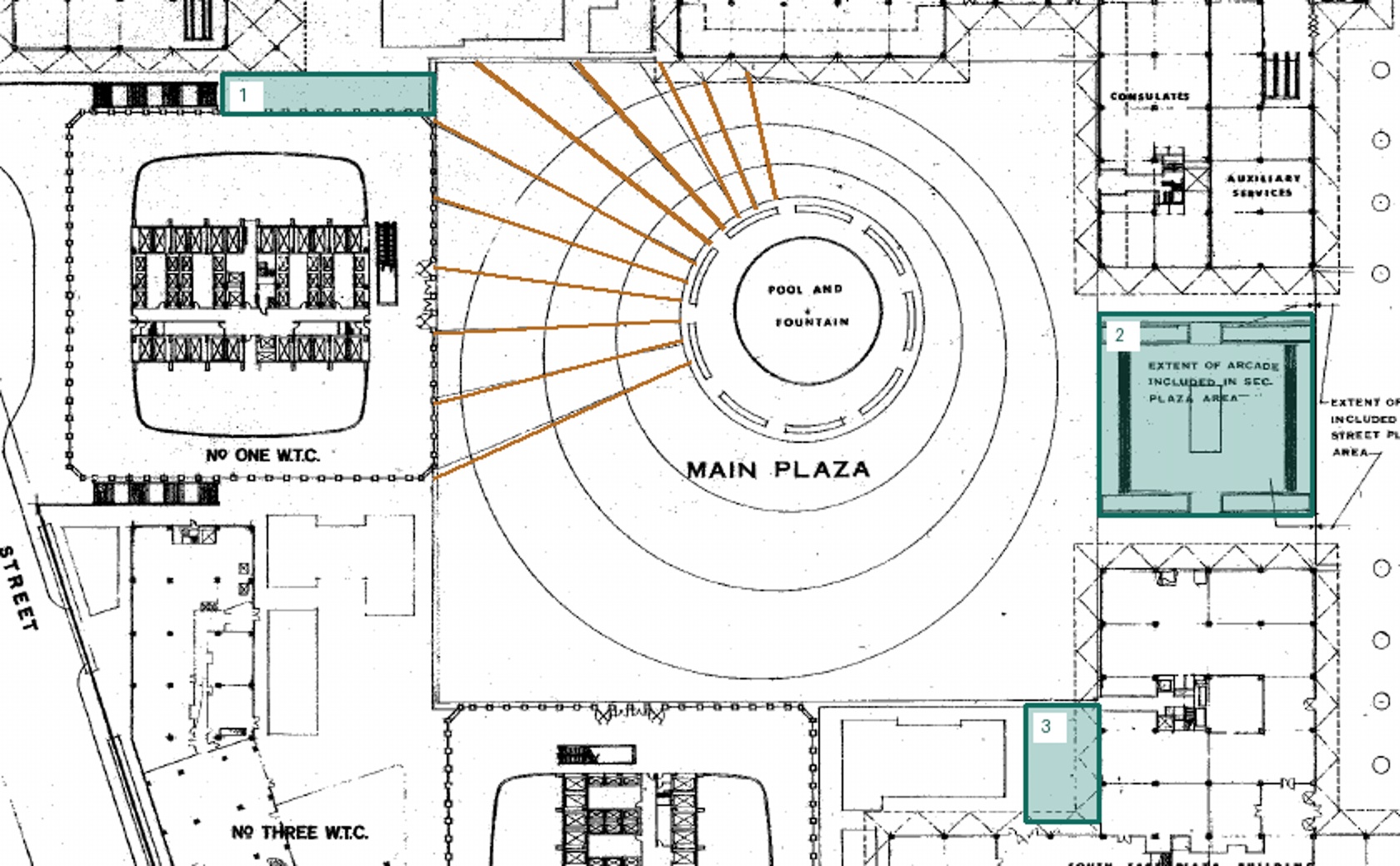
SKA55/84 is an older plan, not a complete 2001 inventory. The 1995 memorial and later changes need separate dated evidence. The source image includes buildings; the model adds ground surfaces only.
Source pixels and evidence record ↗
Main plaza, fountain and planting beds
The larger plaza outline, fountain footprint and three offset paving curves follow the coarsely aligned SKA55/84 plan. The photograph below confirms a lower circular terrace with short stair openings between curved planter beds. Wall heights, soil recess, exact tread count and local levels remain study assumptions.
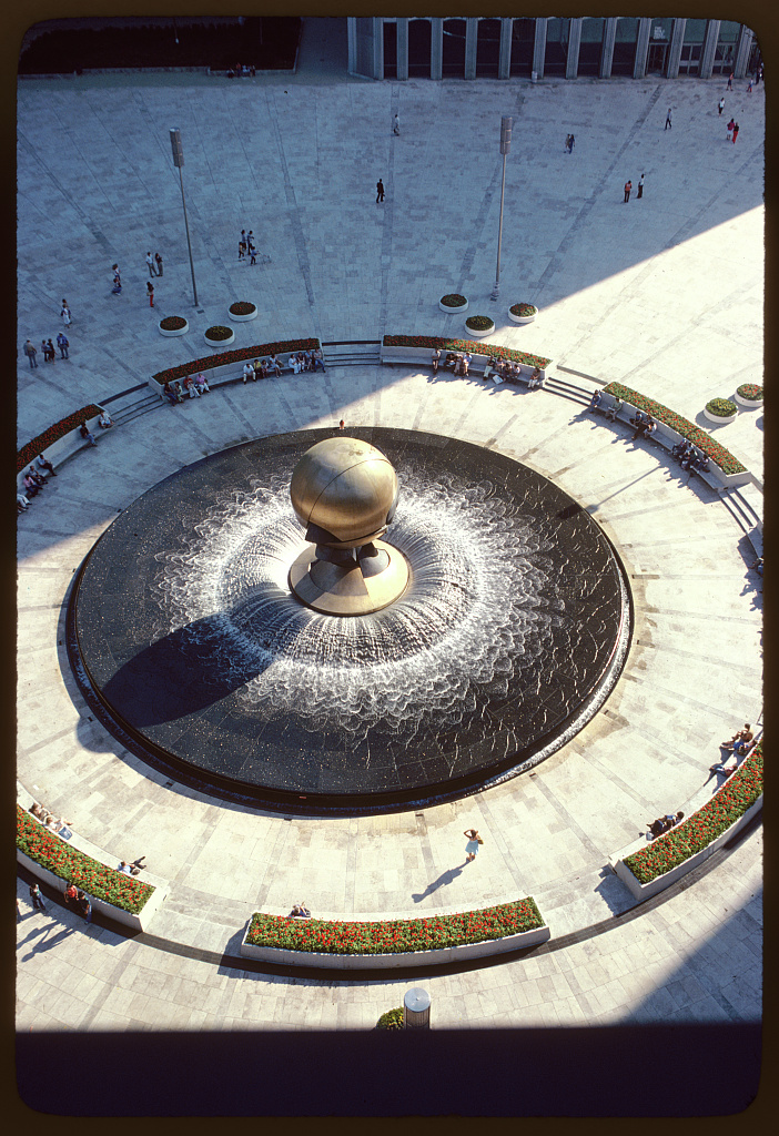
Balthazar Korab, 1976 catalogue date · Library of Congress, ppmsca.71340. No known restrictions on publication.
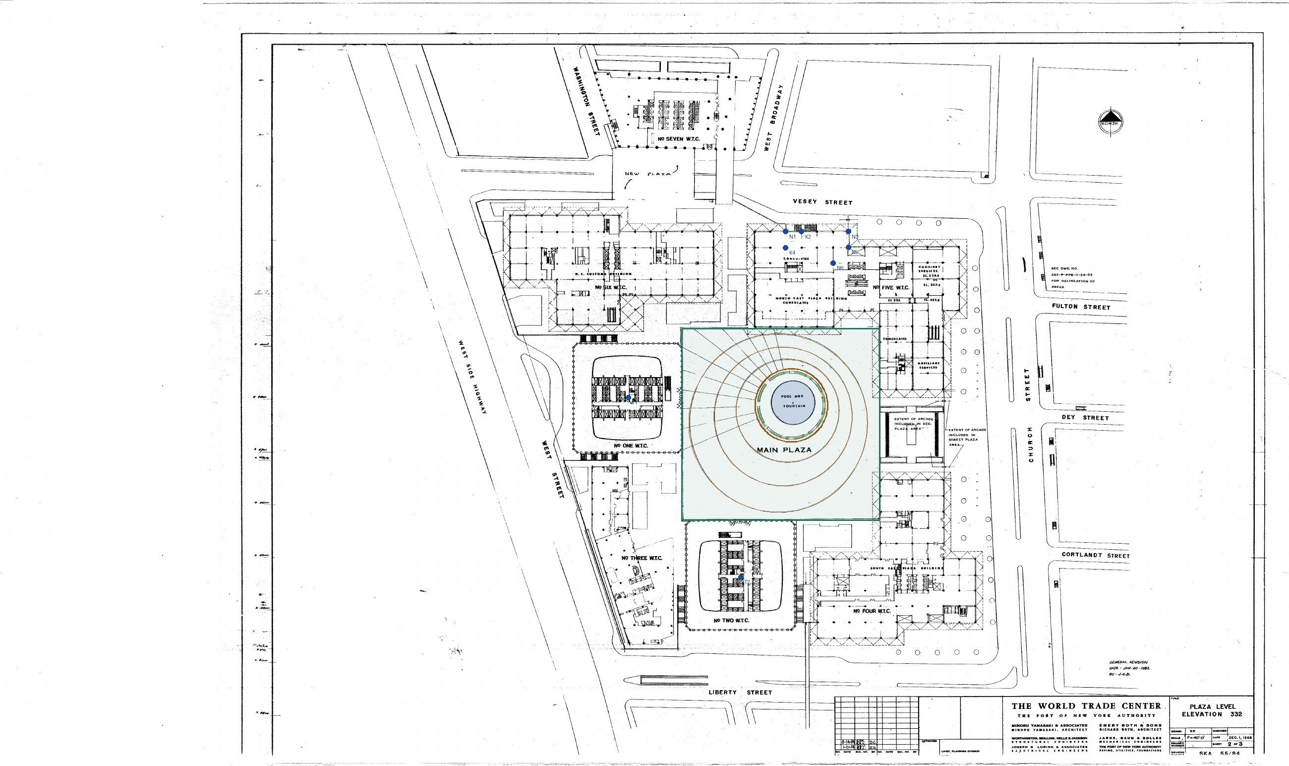
Source plan includes buildings for orientation. Blue points register the drawing; Study 07 aligns the existing WTC 1 / WTC 2 models through their original survey frame.
The source behind the walk
Green traces the two labelled planter footprints on A-E-22. Amber illustrates a path through the available exterior space. The source drawing includes neighboring architecture for orientation. The complex viewer also includes the surrounding building frames.
Inspect the annotated original plan
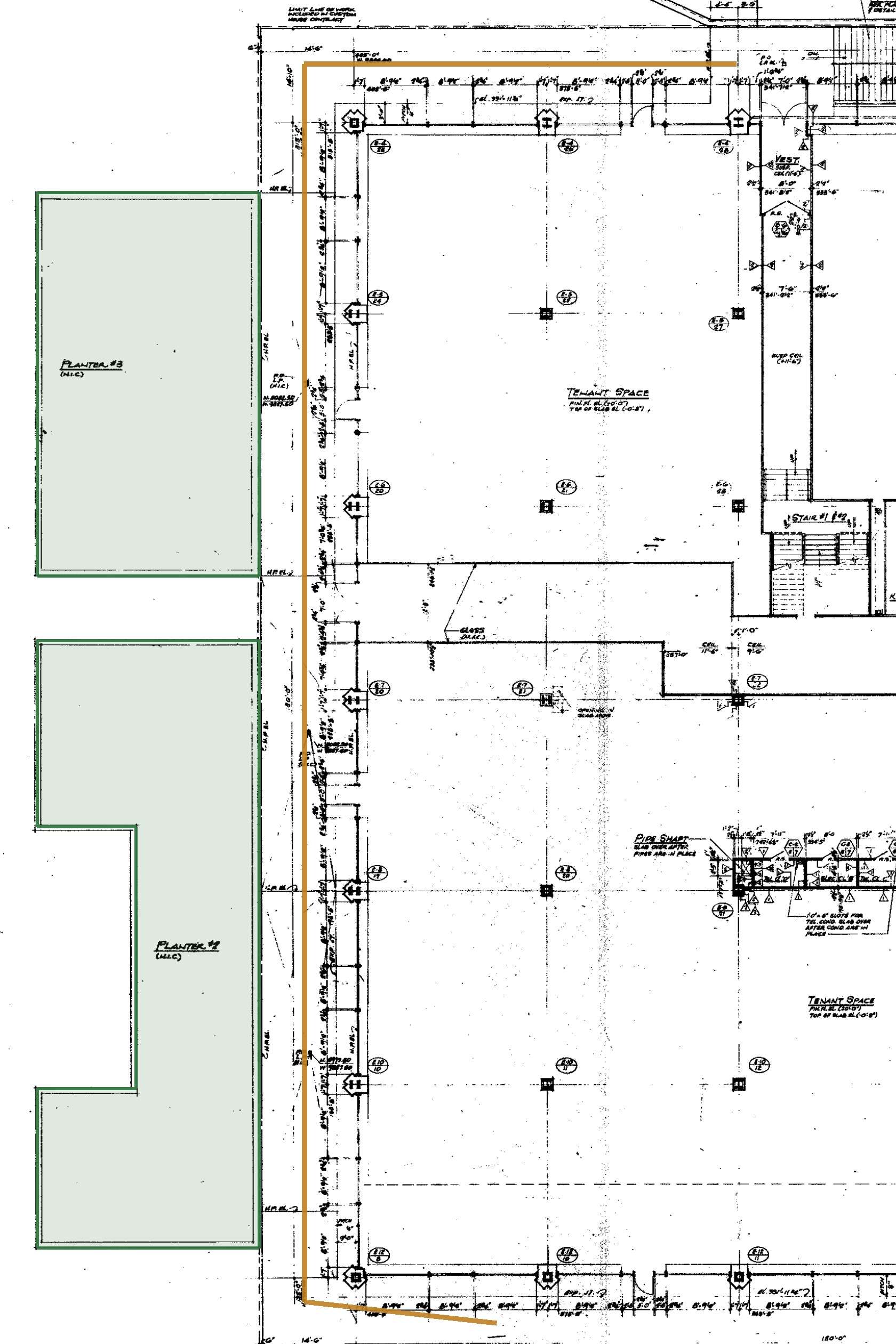
The curb and the stair are separate points
The registered original plan places the V02 curb and PL7 east-end callout about 17 feet apart. Their four-inch elevation difference could describe a sloping sidewalk if both annotations refer to its finished surface. It does not establish a step at the stair foot.
The 3D sidewalk retains a flat-crossfall comparison surface. The dashed line below tests a possible connection without treating it as measured geometry.
Two floor plans, one building grid
A-E-14 is the black concourse layer; A-E-22 is the blue upper-floor layer. Six common building columns set their provisional alignment, with two further columns reserved as checks. The stair’s different visible portions are not used as matching points.
0%: concourse only · 100%: both plans
Amber: default study envelope. Green: curb leaders. Blue: upper floor and common columns. These are older original-design/revision drawings, not established 2001 as-builts. Stored coordinates have more digits than the image measurements justify.
Full A-E-14 ↗ · Full A-E-22 ↗ · Control-point record ↗
Original upper plan · A-E-22
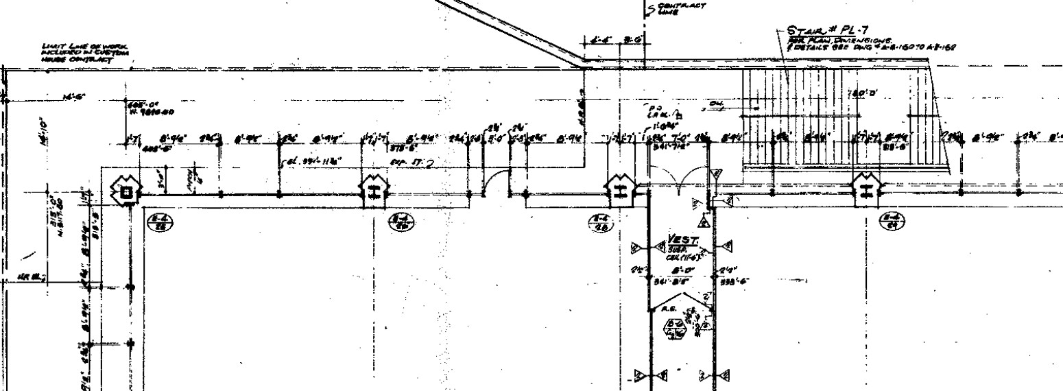
PANYNJ-18324, PDF p.211. Now provisionally aligned through distributed common columns. The blurred western coordinate note is not used as a control. Stair dimensions and later alterations remain unresolved.
Overall form and landing
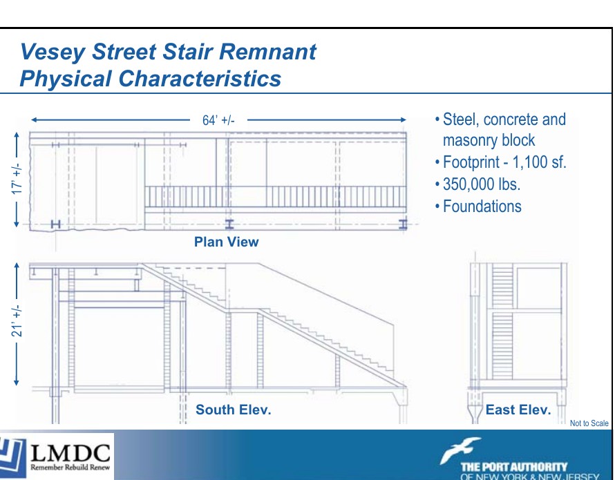
The 2006 drawing supports a landing break and an approximate 64 × 17 ft envelope. Its roughly 21 ft height describes the remnant; it does not establish finished stair rise. The source says “Not to Scale.” A 2007 report instead gives 68 ft overall length.
Port Authority / LMDC, p.11 ↗
Finishes and adjacent escalators
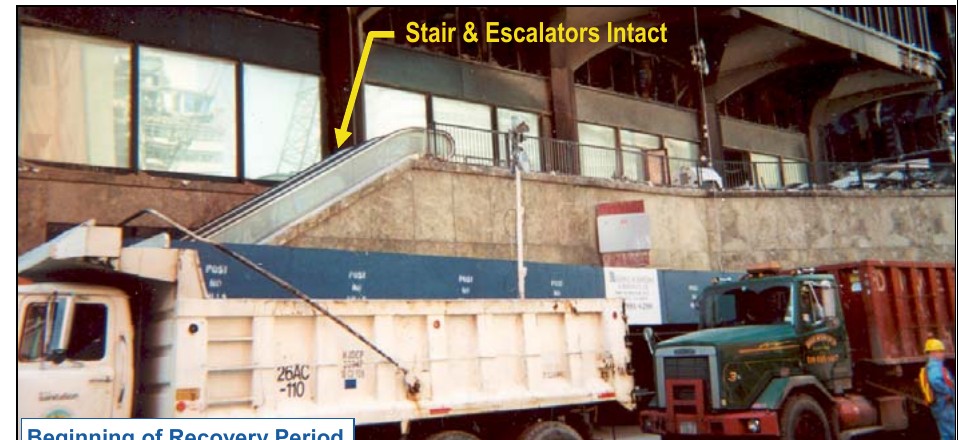
The early recovery view retains the outer finish and escalator enclosure. Recovery photographs help identify parts but do not prove an intact pre-attack condition.
Port Authority / LMDC, p.3 ↗
Subway access is a separate connection
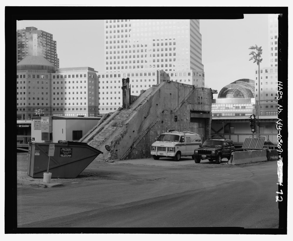
The original plan marks an IRT stair and entry area, separate from the exterior stair. The violet zone in the model reserves that relationship; its opening, headroom, descent and full route have not been measured.
Library of Congress HABS NY-6369, photo 72 ↗